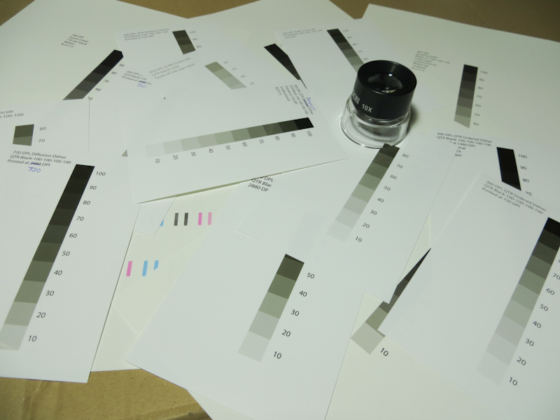
I spent last night printing – just not with the etching press. Instead I used my Epson 3880 to make test strips – a lot of test strips.
My goal was to figure out the right printer settings and workflow in order to print directly to ImagOn plates, bypassing the need for transparencies and eliminating the dedicated aquatint exposure.
As I mentioned in my earlier post, it is possible to incorporate an aquatint-like structure into the image to provide the small ink wells that prevent an open bite in the dark areas. I am currently aware of four approaches for incorporating the aquatint into the inkjet output:
- Printer Driver Dither. In this approach, a gray scale image is converted to a dither pattern of solid black dots in the manufacturer’s printer driver. If your printer driver has a black-only mode, this is one of the best approaches because the dither can be accomplished at any of the printer’s native resolutions.
- 3rd Party RIP Dither. Some printers like the Epson 3880 limit black-only mode to lower resolutions. This can lead to a grainy image in the matrix. One can use a 3rd party RIP like QuadToneRip to generate a maximum resolution dither pattern. The downside of this approach is that it involves a lot of experimentation to get the RIP configured correctly. I’ve also found that the Epson driver seems to generate a smoother dither.
- Photoshop Diffusion Dither. In this approach, a grayscale image is converted to a bitmap using Photoshop’s diffusion dither. Conceptually this is similar to the algorithm in the printer driver and the RIP. In practice, it can generate a lower quality dither on the plate because the dithered image from Photoshop may get dithered again in the printer driver or RIP. One can reduce this effect somewhat by choosing bitmap resolutions that are power-or-2 factors of the printer’s resolution. One can also eliminate any print-time processing by using a driver like GutenPrint.
- Photoshop Stochastic Screen Layer. I describe this approach in my earlier post. The goal is to more accurately mimic the effect of an aquatint screen. In the first three approaches, the density of dots decreases as the image gets lighter. This can have the impact of reducing resolution in the lighter shades. A stochastic screen layer has a uniform dot density across the value scale, and uses gray levels or even colored inks to adjust the value. This approach has a couple of downsides. As with the Photoshop diffusion dither, one has to guard against additional dithering in the printer driver and RIP. The other downside is resolution – the printer only has a limited ability to adjust drop size, so gray levels will still need to generated by some amount of dithering. This means that each pixel in Photoshop will need to correspond to a handful of pixels in the printer.
Last night I focused my efforts on the first two approaches, with my first test using the Epson printer driver at 720dpi. My goals were to figure out sufficient dot density while avoiding excessive dot gain and banding. Factors that impact density include choice of ink, print resolution, print speed, and the color density setting in the advanced media control options. Factors that impact dot gain and banding are paper thickness, platen gap, and drying time per print head pass.
After examining many test prints under a loupe, I finally arrived as some settings that seem like a decent starting point. The results shown below are from the Epson driver with the following settings:
- Media type: Epson Singleweight Matte Paper (this is one of only two media choices that enable black-only printing – other Epson printer models enable black-only printing for a wider variety of media and resolutions).
- Color: Black
- Ink: Matte Black (only choice allowed for this media type)
- Print Quality: Quality (720dpi – the only resolution supported for black-only)
- Paper thickness: 15 (1.5mm)
- Platen Gap: Wider
- Color Density: default value
- Drying Time per Print Head Pass: default value
Using these settings, I printed a test strip directly onto a plate consisting of ImagOn laminated to 0.030″ polycarbonate. The plate was laminated the day before printing and I waited another 24 hours after printing before exposing and developing. The plate was exposed on a Nuarc 26-1K exposure unit for 20 units. I did not use the vacuum frame. Development was the standard 9 minutes in a room temperature solution consisting of 10g soda ash per liter of distilled water.
Overall the plate looks pretty good.
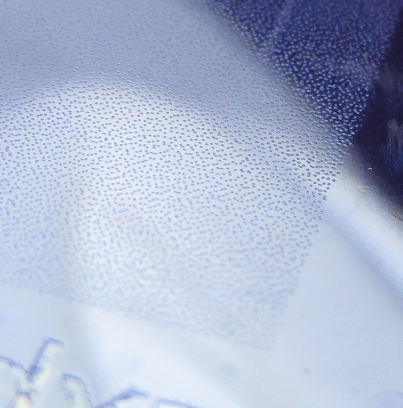
Here’s a closeup of the 10% density portion of the plate. The pits are well formed and go all the way to the surface of the polycarbonate plate.
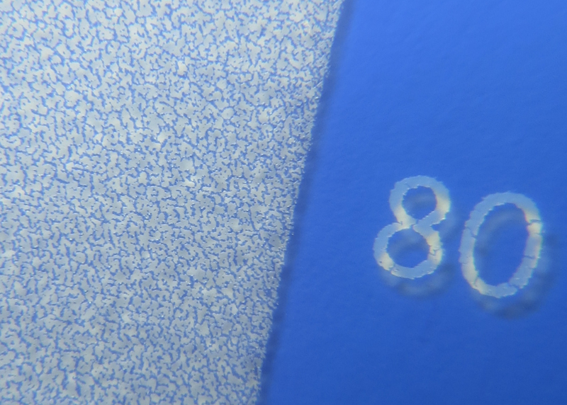
Here’s the pattern on the plate at 80% density. Again, the pits go all the way to the polycarbonate plate, and the ridges seem full thickness. This matrix looks very similar to the best plates I’ve made with an aquatint screen.
The aquatint pattern in the matrix on this plate is almost perfect! Unfortunately the matrix shows an unacceptable amount of printer banding.
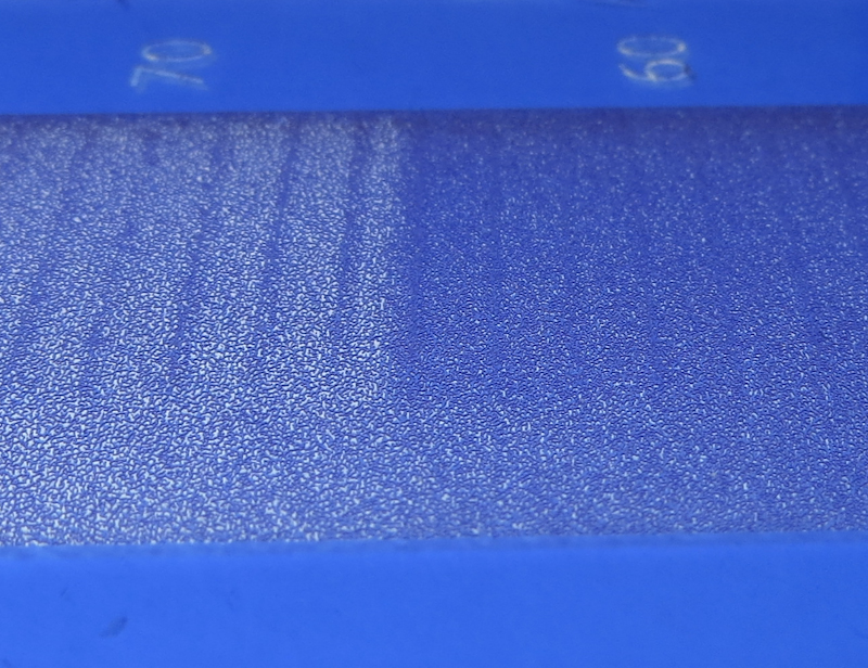
The big unresolved issue is the banding you can see here at 60% and 70%. The banding appears throughout the value scale, but is more pronounced in the darks.
Printer banding has many potential causes, but the most common are misaligned print heads and head strikes due to incorrect paper thickness, insufficient platen gap, dust and particulate on the print head itself, and warped media. The photo below shows clear evidence of head strikes. The fact that the banding does not go all the way across the plate suggests that the plate wasn’t completely flat, allowing a head strike for a portion of the scan.
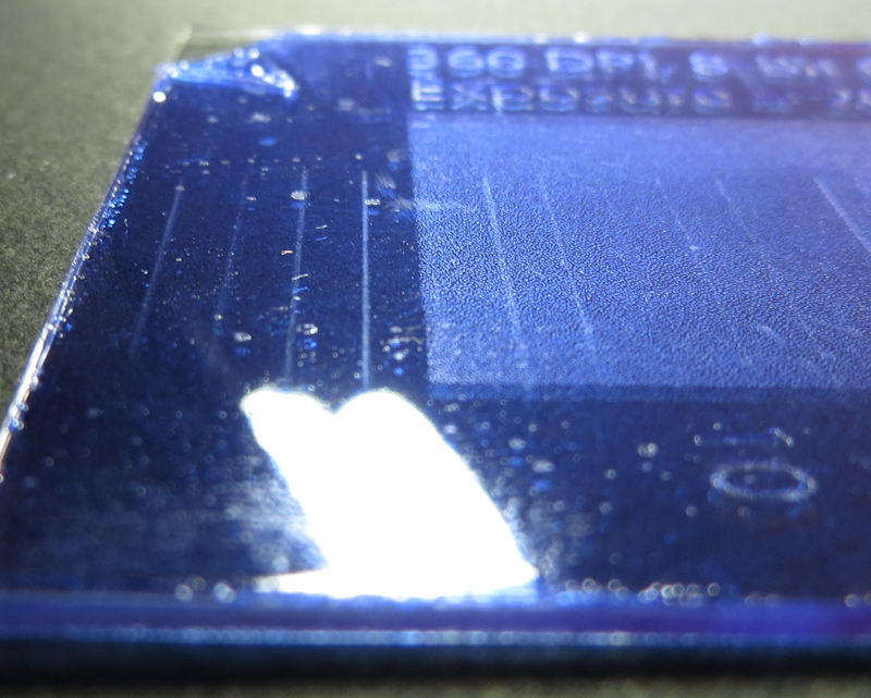
This image shows evidence that the banding is produced by head strikes. The vertical scratches on the left of the plate are in a non-printing area, thus indicating that the head is dragging across the plate.
It’s been a lot of work to get to this point, but I am pretty happy with the results. I am confident that I can address the banding and then I will do a PDN-like calibration to generate Photoshop adjustment curves to linearize the ImagOn response. Stay tuned for another exciting episode!

